How to Increase Welding Consistency with Robotic Systems?

Time:2026-09-10 Author:Madeline
0%

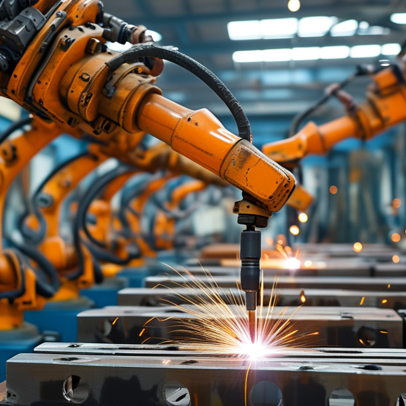
Manufacturers often ask, “how do robotic welding systems increase consistency?” The answer begins with control. Robotic systems repeat programmed torch paths, travel speeds, weld angles, and wire-feed settings. They do not tire during a long production shift. They also reduce variation between operators, workstations, and production days.

Dr. John Norrish, a respected welding automation researcher and author, captures this principle clearly: “Automation does not replace welding knowledge; it makes that knowledge repeatable.” His observation matters on the shop floor. A robot can return to the same joint within a narrow programmed tolerance. Sensors can detect part position, while monitoring systems record voltage, current, and arc time. This creates a visible process history instead of relying only on memory.

However, robotic welding is not a magic solution. Poor joint design, inaccurate fixtures, contaminated material, or unstable wire delivery can still produce defects. A robot may repeat the wrong instruction perfectly. That uncomfortable detail deserves attention. Consistency improves only when engineers validate parameters, inspect welds, and maintain equipment routinely.

In practical use, an operator may load a steel bracket into a fixture, confirm its locating pins, and start the cycle. The robot follows the approved path with controlled movement. A quality technician then checks bead shape, penetration, and dimensional results. Over time, collected data can reveal drift before it becomes a costly batch problem.

The strongest systems combine programming discipline, skilled supervision, reliable fixturing, and regular feedback. They improve repeatability, but human judgment remains essential. That balance should guide any serious investment in robotic welding.
How to Increase Welding Consistency with Robotic Systems?

Defining Welding Consistency in Robotic Manufacturing

Defining welding consistency in robotic manufacturing starts with measurable evidence, not visual confidence. A consistent weld repeats its bead width, penetration, leg size, travel speed, and heat input within approved limits. It also produces stable results across shifts, operators, materials, and joint positions. ISO 5817 provides quality levels for imperfections, while process records reveal whether production actually meets them.

The International Federation of Robotics reported 541,302 industrial robots installed worldwide in 2023. This growth increases output, but automation alone cannot guarantee weld quality. Deloitte’s 2023 Smart Manufacturing survey found that 86% of manufacturing leaders viewed smart operations as important for future competitiveness. Yet inconsistent fixturing, dirty surfaces, wire variation, or incorrect torch angles can still create porosity and undercut. The uncomfortable truth is simple: a robot repeats errors very efficiently. NIST research also emphasizes calibrated sensing and traceable measurement for reliable robotic processes.

Tips: Define consistency with measurable limits. Track current, voltage, travel speed, gas flow, and wire feed rate. Use scheduled torch checks and verify fixture position before production. Capture images and weld data for every critical batch. Train technicians to question abnormal patterns, even when the bead looks acceptable. A perfect-looking weld can hide incomplete fusion. That possibility deserves attention. Review failed parts, not only successful ones, and adjust thresholds when real production exposes weaknesses.

How to Increase Welding Consistency with Robotic Systems?

Robotic welding improves repeatability by maintaining a consistent torch path, travel speed, and welding position. The benchmark below compares common production consistency indicators between manual and robotic welding processes.

Selecting the Right Robotic Welding System

How to Increase Welding Consistency with Robotic Systems?

Selecting the Right Robotic Welding System

Selecting a robotic welding system starts with the part, not the robot. Review material type, thickness, joint design, and production volume together. A thin stainless assembly may need precise arc control and gentle wire feeding. A heavy steel frame may demand higher payload capacity and longer duty cycles. Measure actual tolerances, too. A robot cannot correct every variation.

Look closely at the work envelope and fixture design. The torch must reach each joint without awkward wrist angles. Fixtures should hold parts firmly while allowing quick loading and safe access. Useful systems may include seam tracking, vision sensors, touch sensing, or automatic torch cleaning. These features improve repeatability, but they also add setup and maintenance demands. Keep that trade-off visible.

Programming should match your team’s real skills. A clear interface helps operators adjust travel speed, voltage, and weave patterns without guessing. Request a sample weld using your most difficult joint. Inspect penetration, bead profile, spatter, and cycle time. Test several part variations. One successful demonstration proves very little.

Safety systems, guarding, ventilation, and documented training require equal attention. Review service access and spare-part availability before installation. A compact cell may save floor space but limit future expansion. Our early assumption that more sensors always meant better quality was wrong. Poorly calibrated sensors can create new inconsistencies. Choose measurable performance over impressive specifications.

Preparing Materials, Fixtures, and Welding Parameters

How to Increase Welding Consistency with Robotic Systems?

Robotic welding begins before the arc starts. Material preparation controls joint fit-up, surface condition, and wire feeding. Remove oil, mill scale, and moisture from contact areas. Small errors multiply. A 1 mm gap change can alter penetration and bead shape. Record material grade, thickness, lot number, and edge condition. This information supports traceability and faster troubleshooting.

Fixtures must locate parts firmly without restricting thermal movement. Use hardened reference points and inspect them during each shift. In practical production, worn locators often create more variation than the robot itself. Check clamping pressure, torch access, and cable routing before production runs. The International Federation of Robotics reported 541,302 industrial robot installations worldwide in 2023, showing the scale of automation. However, robot adoption alone does not guarantee stable weld quality.

Welding parameters should match the joint, position, and material condition. Control voltage, amperage, travel speed, shielding gas flow, and torch angle. Store approved parameter windows, not only one nominal setting. American Welding Society workforce forecasts indicate that the industry may face a shortage of more than 300,000 welding professionals by 2028, increasing pressure for dependable automated processes. Sensors can detect deviations, but they cannot correct poor preparation. Repeatable does not mean perfect. Operators should review weld samples, log defects, and adjust fixtures when evidence supports change. A clean setup may still fail during heat buildup. That possibility deserves attention.

How to Increase Welding Consistency with Robotic Systems? - Preparing Materials, Fixtures, and Welding Parameters

Practical control dimensions for a robotic GMAW process on clean, low-carbon steel components. Values are representative production targets and should be validated through procedure qualification and weld testing.

Control Area Control Dimension Recommended Target Acceptable Variation Verification Method Consistency Benefit
Material Preparation Base material thickness 3.0 mm nominal ±0.15 mm for controlled production lots Measure with a calibrated micrometer at incoming inspection Keeps heat input and penetration requirements stable
Material Preparation Surface cleanliness Remove oil, paint, rust, scale, and moisture from the joint area Clean at least 25 mm from both sides of the joint Visual inspection and solvent-wipe check before loading Reduces porosity, spatter, arc instability, and lack of fusion
Material Preparation Joint root gap 1.0 mm 0.5–1.5 mm Use calibrated gap gauges at multiple points along the joint Prevents excessive penetration or incomplete root fusion
Material Preparation Joint mismatch ≤0.5 mm Maximum 10–15% of the thinner material thickness Check with a flushness gauge before welding Maintains a predictable torch-to-joint relationship
Fixtures Part location repeatability Within ±0.25 mm from the programmed datum Maximum ±0.50 mm for non-critical features Run a fixture capability study with a coordinate measurement device Reduces seam-tracking corrections and weld-to-weld variation
Fixtures Clamping force Sufficient to prevent movement without deforming the joint Use the same verified clamp setting for every cycle Record clamp pressure or force during setup verification Controls distortion and keeps the joint gap consistent
Fixtures Fixture accessibility Maintain at least 25 mm clearance around the torch and nozzle No contact with clamps, locators, or adjacent components Perform a dry robot path and collision check at reduced speed Prevents contact faults and protects torch orientation
Fixtures Datum and locator condition Clean, secure, and free from weld spatter Inspect at every shift change or after 50–100 cycles Use a documented fixture inspection checklist Avoids gradual positional drift during production
Welding Parameters Shielding gas flow rate 15–20 L/min for an indoor, low-draft work cell Keep within the qualified procedure range Verify with a calibrated flow meter at the torch Limits atmospheric contamination and porosity
Welding Parameters Contact-tip-to-work distance 12–15 mm Approximately ±2 mm during the weld Confirm torch setup and review robot path clearance Stabilizes current transfer, arc length, and deposition rate
Welding Parameters Torch work angle Approximately 45° for a symmetrical fillet joint Within ±5° of the programmed angle Use a digital angle gauge during teach-point verification Improves sidewall fusion and bead symmetry
Welding Parameters Travel angle 10–15° push angle for common GMAW fillet applications Within ±5° Confirm the torch orientation in the robot program Reduces excessive penetration changes and undercut risk
Welding Parameters Arc voltage 19–21 V for a typical 3.0 mm steel fillet weld setup Remain within the qualified welding procedure range Monitor the power source display and record alarm history Maintains consistent arc length and bead profile
Welding Parameters Wire feed speed Approximately 5.5 m/min with 1.0 mm solid wire Use the qualified procedure range; verify actual output periodically Compare programmed and measured wire feed speed Controls deposition rate and weld size
Welding Parameters Travel speed 350–450 mm/min, depending on required weld size Maintain programmed speed unless a qualified adaptive strategy is used Review robot motion data and inspect bead dimensions Keeps heat input and weld reinforcement consistent
Process Monitoring Interpass temperature Below 150°C for common low-carbon steel procedures Follow the approved welding procedure specification Measure with a contact thermometer or calibrated infrared device Controls excessive heat accumulation and distortion
Process Monitoring Wire and nozzle condition Clean nozzle, centered contact tip, and undamaged wire Replace or clean at defined cycle intervals and when arc quality changes Inspect before each shift and after abnormal arc events Reduces arc wandering, inconsistent shielding, and spatter
Quality Verification Fillet weld leg size Meet the drawing or procedure requirement; example: 6 mm Use the applicable acceptance standard and engineering specification Measure with a certified fillet weld gauge during first-piece and periodic inspection Confirms that programmed parameters produce the required strength
Quality Verification Robot program control Lock approved programs and require revision-controlled changes Only authorized personnel may edit welding paths or parameters Audit program version, parameter logs, and change history Prevents undocumented changes from affecting production consistency

Important: Actual values depend on material grade, joint design, wire diameter, shielding gas composition, weld position, required weld size, and the approved welding procedure. Validate all settings through qualified procedure testing before production use.

Programming and Calibrating the Robotic Welding Process

How to Increase Welding Consistency with Robotic Systems?

Programming and calibrating a robotic welding process begins with physical accuracy. A technician checks the torch TCP using four approach points, then verifies the workpiece frame. A 1.5-millimeter TCP error can shift the arc across a long seam. That error is small. Its effect is not.

Programming should reflect the joint, not merely the drawing. Offline paths help assess reach, while critical points often need teaching at the fixture. Record travel speed, wire feed, voltage, gas flow, and torch angle in every program. Use test coupons before production. The International Federation of Robotics reported 553,052 industrial robots were installed worldwide in 2022. However, installation numbers do not prove weld quality. Poor calibration can automate inconsistency.

A reliable process includes TCP checks, fixture inspections, and traceable parameter changes. The American Welding Society projects a U.S. welding workforce shortfall of about 330,000 workers by 2028. This pressure increases the value of repeatable programming, but it may also encourage rushed deployment. I have seen teams adjust arc settings while ignoring cable drag or a loose fixture. That was a mistake. Capture bead measurements, images, and operator observations after each trial. If the robot repeats one defect, inspect the coordinate system before changing every parameter. Human review still matters.

Monitoring, Inspecting, and Improving Weld Quality

Robotic welding becomes consistent when monitoring starts before defects become visible. In a production cell, sensors can record arc current, voltage, travel speed, wire feed, and torch angle. A sudden voltage change may reveal contamination, poor fit-up, or an unstable arc. Operators can then inspect the bead while the part is still warm, instead of discovering failures during final assembly.

The International Federation of Robotics reported 541,302 industrial robots installed worldwide in 2023. That scale increases the value of reliable inspection data. Vision systems can measure bead width, undercut, spatter, and missing welds. Non-destructive testing can examine hidden flaws, especially in critical joints. ISO 17637 supports visual testing practices, while ISO 5817 defines quality levels for imperfections. These standards help convert inspection into repeatable decisions.

Traceability matters too. Each weld should connect to a program version, material batch, operator review, and inspection result. The American Welding Society workforce report projects a need for 330,000 new welding professionals by 2026. Automated records can reduce dependence on memory and scarce expertise. Still, automation is not perfect. A clean-looking bead can hide incomplete fusion. A sensor can also drift without warning. Regular calibration, sample testing, and human review remain necessary. That part is easy to underestimate.

FAQS

: What defines consistency in robotic welding?

: Consistency means repeating bead width, penetration, leg size, speed, and heat input within approved limits. It must remain stable across shifts, materials, operators, and joint positions.

Can automation guarantee good weld quality?

No. A robot can repeat an incorrect torch angle, poor fixture position, or contaminated surface very efficiently. Automation improves repeatability, but it does not replace process control.

Which welding data should technicians monitor?

Track arc current, voltage, travel speed, gas flow, wire feed rate, and torch angle. Sudden voltage changes may indicate contamination, poor fit-up, or an unstable arc.

How can inspection detect hidden weld problems?

Visual inspection can identify bead width, undercut, spatter, and missing welds. Non-destructive testing can reveal hidden flaws in critical joints. A clean-looking bead can still hide incomplete fusion.

Why are calibration and scheduled checks important?

Sensors may drift without obvious warning. Scheduled calibration supports reliable measurements and repeatable decisions. Torch checks and fixture verification should happen before production.

What information should each weld record contain?

Connect each weld with its program version, material batch, inspection result, and operator review. Images and process data should be saved for critical production batches.

When should operators inspect a robotic weld?

Inspect the bead while the part is still warm when possible. Early inspection can reveal problems before final assembly. Do not wait for failure.

How should teams respond to abnormal patterns?

Question unusual current, voltage, speed, or bead changes, even when the surface looks acceptable. Review failed parts, not only successful ones. Some thresholds may need adjustment after real production exposes weaknesses.

Conclusion

Welding consistency in robotic manufacturing means producing uniform welds with stable penetration, bead size, strength, and appearance across every workpiece. This article explains how to select a robotic welding system according to production volume, part geometry, material requirements, and workspace limitations. It also highlights the importance of properly preparing materials, securing accurate fixtures, and setting suitable welding parameters before production begins. These foundations help reduce variation and create a reliable, repeatable process.

The guide also explores how to program and calibrate the robot so its movement, torch position, speed, and wire delivery remain precise. Regular monitoring and inspection can identify defects, equipment drift, or process changes before they affect large batches. By reviewing weld data, maintaining equipment, and adjusting parameters systematically, manufacturers can continue improving quality and efficiency. Overall, it answers the question, “how do robotic welding systems increase consistency,” by showing how automation combines repeatable motion, controlled settings, and ongoing quality management.

Madeline

Madeline

Madeline is a dedicated marketing professional with a wealth of expertise in our company's core offerings. With a keen understanding of the industry, she brings a unique perspective to her role, consistently delivering high-quality content that highlights the superior aspects of our products. As......