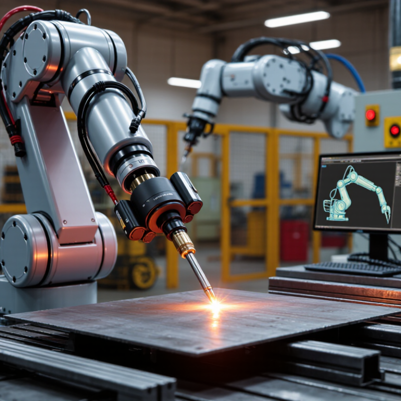
How to Program Welding Robot Arms in 2026?

Time:2026-10-10 Author:Amelia
0%

How to program welding robot arms in 2026 depends on more than learning a software interface. It requires practical knowledge of welding behavior, robot motion, fixture design, and production control. Many teams ask, “are welding robot arms difficult to program?” The honest answer is: they can be, especially during the first setup. A technician must define the tool center point, select welding parameters, teach approach angles, and manage torch clearance. A few millimeters can change bead shape, cause spatter, or create an incomplete joint. Small errors matter.

Modern platforms offer offline programming, digital twins, automatic path generation, and sensor-based correction. These features reduce repetitive teaching, but they do not replace skilled judgment. A virtual path may look perfect while the real torch touches a fixture. That still happens. Reliable programming combines manufacturer manuals, qualified welding procedures, operator experience, and careful production trials. It also requires documented safety checks before anyone runs the cell. Guarding, emergency stops, interlocks, and controlled testing remain essential. Do not trust simulation alone.

This guide explores the programming process used in real robotic welding environments. It covers coordinate systems, joint teaching, seam tracking, parameter selection, troubleshooting, and maintenance feedback. Examples will focus on practical details, such as checking a torch at a 45-degree angle or reviewing a bead after a short test weld. The goal is not to promise effortless automation. It is to explain where modern tools help, where they fail, and how disciplined technicians build repeatable results. Expect refinement. Good programs improve through evidence.

How to Program Welding Robot Arms in 2026?

Welding Robot Arms: Core Components, Axes, and Control Systems

How to Program Welding Robot Arms in 2026?

A welding robot arm is not just a moving torch. Its performance depends on the arm, welding power source, wire feeder, sensors, controller, and safety circuits. The International Federation of Robotics reported 541,302 industrial robot installations worldwide in 2023. That scale shows why structured programming matters.

A six-axis arm usually provides three positioning axes and three wrist axes. The first axes place the torch near the joint. The wrist axes control torch angle, travel direction, and work angle.

Small errors become visible as uneven beads, undercut, or excessive spatter. I have found that teaching points alone is rarely enough.

The programmer must also define approach paths, weaving patterns, speed, voltage, current, and gas flow.

The controller coordinates motion with the welding sequence. It starts shielding gas, feeds wire, controls the arc, and stops the process safely. Position feedback from encoders supports repeatable movement, while touch sensing can locate inconsistent parts.

ISO 10218 guidance remains important for industrial robot safety and integration. However, real workshops are less perfect than simulations. Fixtures shift. Steel bends. Torch nozzles collect residue.

Test the first weld slowly.

The International Federation of Robotics also recorded more than 4.2 million industrial robots operating globally at the end of 2023. That installed base increases demand for maintainable programs, clear fault messages, and documented parameter changes.

A reliable program should be easy to inspect, not merely impressive during a demonstration.

Safety Checks and Workspace Setup Before Robot Programming

Before programming a welding robot arm, treat the cell as an active industrial hazard, not an empty workbench. Walk the perimeter and inspect fencing, gates, interlocks, emergency stops, and warning lights. Test every safeguard under documented procedures. A disabled interlock is never a shortcut. Confirm power isolation before entering the cell, and release stored pneumatic or hydraulic energy. Wear suitable eye, hand, hearing, and flame-resistant protection during setup. Follow applicable safety rules and the cell’s risk assessment.

Clear cables, tools, gas hoses, and scrap from the robot’s travel path. The floor should be dry, uncluttered, and bright enough to reveal leaks or sharp edges. Secure the workpiece in a rigid fixture, then compare its position with the programmed reference. Check torch clearance from clamps, walls, and the table at every expected orientation. A few millimeters can become a collision. Inspect shielding gas connections, flow, extraction, and ventilation before creating an arc. Keep combustible materials outside the hot-work area.

Use low-speed teach mode and keep the control pendant under direct supervision. Run the path without arc power first. Watch wrist rotation, cable movement, and operator access. A practical lesson is that small fixture shifts can defeat careful programming. I still recheck them. Verify the tool center point, work coordinates, and collision limits after every adjustment. Have a qualified person review the dry run before welding begins. If visibility is poor, stop and improve the setup instead of guessing.

How to Program Welding Robot Arms in 2026?

Safety-distance calculation before robot programming

The chart applies the ISO 13855 calculation model S = K × T + C, using an approach speed of 1,600 mm/s and an intrusion allowance of 120 mm. Actual stopping time must be measured for the complete robot, controller, tooling, and safety circuit before finalizing guards or access zones.

Pre-programming workspace checks

  • Confirm perimeter guarding, gates, interlocks, and emergency stops are functional.
  • Measure the robot stopping time and verify the calculated safety distance.
  • Define the robot reach envelope, tool envelope, pinch points, and restricted zones.
  • Remove loose objects, combustible materials, and welding obstructions from the cell.
  • Check cable routing, grounding, shielding, ventilation, and welding-fume extraction.
  • Use reduced-speed teaching mode and authorize only trained personnel for setup.

Creating the Welding Path, Tool Position, and Motion Sequence

How to Program Welding Robot Arms in 2026?

Programming a welding robot begins with a reliable weld path, not a colorful simulation. In shop-floor commissioning, I define the workpiece frame before teaching points. The robot must approach the joint smoothly, maintain torch angle, and leave enough clearance for cables. Small errors become visible quickly.

Create the path around the joint’s actual geometry. Set the tool center point at the wire tip, then verify it with four-point calibration. A 2-millimeter TCP error can change the arc position along a long seam. Add approach, weld, and retract points. Keep wrist rotation controlled near corners. Avoid sudden speed changes. They can cause spatter, undercut, or unstable bead width.

The International Federation of Robotics reported 541,302 industrial robot installations worldwide in 2023, showing why repeatable programming skills matter across expanding production systems.

The motion sequence should match the welding process. Set travel speed, arc start delay, crater fill, and weaving parameters separately. Use simulation for reachability, but inspect the physical weld. A perfect model can still hide fixture deflection. I have seen a path pass collision checks and fail after heat distortion. That mistake deserves review.

Deloitte’s 2024 Smart Manufacturing and Operations Survey found that 86% of manufacturers view smart manufacturing as a major competitiveness driver within five years.

Human verification remains essential. Safety checks should follow applicable robot and welding standards before automatic operation.

Setting Welding Parameters, Sensors, and Seam-Tracking Functions

How to Program Welding Robot Arms in 2026?

Setting Welding Parameters, Sensors, and Seam-Tracking Functions

Programming welding robot arms in 2026 demands more than copying taught points. Start with joint type, material, thickness, and torch angle. Set current, voltage, wire-feed speed, travel speed, and gas flow as one process window. Record actual arc values, not only controller commands. The International Federation of Robotics reported 541,302 industrial robots installed worldwide in 2023, according to World Robotics 2024. That growth increases pressure for repeatable programming and measurable quality.

Sensors make the program more resilient. A touch sensor can find the plate edge before the arc starts. Through-arc sensing can correct lateral drift during weaving. Laser vision can map gaps, missing tacks, and changing joint geometry. Seam tracking needs calibrated offsets, filtered signals, and defined correction limits. Check TCP accuracy after every torch change. I still recommend a dry run with the wire retracted. Small errors become expensive at production speed. ISO 10218 guidance also supports documented risk assessment and validated operating modes.

Tips: Store each parameter set beside its joint drawing. Use sample coupons before live parts. Watch the first three welds through sensor data, not only bead appearance. If tracking hunts side to side, reduce gain before changing speed. Review heat input after cooling. A clean bead can hide excessive penetration or distortion. I sometimes trust stable-looking data too quickly, so repeat tests across different shifts.

How to Program Welding Robot Arms in 2026? - Setting Welding Parameters, Sensors, and Seam-Tracking Functions
Programming Area Parameter or Function Typical Starting Range or Setting Programming Consideration Verification Method
Process Setup Welding process GMAW/MIG-MAG for most carbon-steel robotic applications Select the process according to material, joint design, deposition rate, shielding gas, and required weld quality. Confirm the approved welding procedure and run a controlled test coupon.
Process Setup Wire diameter 0.9–1.2 mm for common automated steel fabrication Use a larger wire for higher deposition rates when the power source, torch, and joint access allow it. Check wire feeding stability, contact-tip condition, and weld appearance.
Welding Parameters Welding current Approximately 120–280 A for many steel fillet and groove welds Higher current generally increases deposition and penetration but also increases heat input and distortion risk. Validate penetration, bead profile, spatter level, and heat-affected-zone behavior.
Welding Parameters Arc voltage Approximately 18–30 V, depending on transfer mode and wire size Voltage affects arc length and bead width. Set it together with wire-feed speed rather than independently. Observe arc stability and measure weld dimensions on a sample part.
Welding Parameters Wire-feed speed Approximately 3–12 m/min for typical solid-wire steel applications Wire-feed speed is closely related to welding current and must match the selected material and wire diameter. Confirm stable feeding, consistent arc transfer, and the required deposition rate.
Welding Parameters Travel speed Approximately 200–800 mm/min for many robotic fillet welds Reduce speed for thicker sections or larger weld sizes, while avoiding excessive heat input and overwelding. Calculate heat input and inspect leg length, throat size, undercut, and overlap.
Welding Parameters Shielding-gas flow rate Approximately 12–20 L/min for indoor GMAW applications Excessive flow can create turbulence and draw air into the shielding zone. Protect the arc from drafts. Check gas hoses, regulator operation, nozzle condition, and porosity results.
Welding Parameters Contact-tip-to-work distance Approximately 10–18 mm for common short-arc and pulsed setups Keep the distance consistent because it influences current, arc length, penetration, and wire resistance. Use a programmed torch path and inspect the distance at the start, middle, and end of the seam.
Motion Programming Approach and retract points Approach from a safe clearance point; retract after arc termination Use separate approach, weld-start, weld-end, and retreat points to reduce collision and spatter risks. Run the program in reduced-speed teach mode before enabling the arc.
Motion Programming Welding orientation Maintain the programmed work angle and travel angle consistently Typical fillet-weld starting points are about 45° work angle and 5–15° travel angle, adjusted for the joint. Use a gauge or fixture reference and inspect bead placement on a test weld.
Motion Programming Weaving pattern No weave for narrow welds; triangular, crescent, or zigzag weave for wider joints Set weave width, frequency, dwell time, and synchronization with travel speed. Avoid excessive dwell at the toes. Verify sidewall fusion, bead profile, and maximum permitted weave width.
Sensors Touch sensing Use before welding to locate part edges, gaps, or fixture variation The torch or sensing wire contacts a conductive surface at low energy to establish a corrected workpiece reference. Check repeatability across multiple parts and confirm that contact does not damage the component.
Sensors Through-arc seam tracking Use during GMAW when joint geometry produces measurable current variation The controller compares signals during a controlled weave and adjusts the path laterally or vertically. Tune tracking gain, weave amplitude, frequency, and response limits using representative joints.
Sensors Laser seam tracking Use for variable gaps, unknown seam locations, or demanding fit-up conditions Define the scan window, stand-off distance, filtering, measurement rate, and allowable correction range. Test performance against surface reflectivity, spatter, joint gaps, and changes in part presentation.
Sensors Arc monitoring Monitor current, voltage, wire-feed speed, gas flow, and arc-on status Set alarm thresholds and data logging so the program can detect burnback, wire interruption, or unstable arc conditions. Simulate fault conditions safely and confirm that the robot stops or enters the defined recovery routine.
Seam Tracking Correction limits Set conservative lateral and vertical correction limits based on joint tolerance Limits prevent the tracker from following spatter, an incorrect edge, or a severely misaligned component. Introduce controlled part-position deviations and confirm that the robot remains within the safe weld zone.
Seam Tracking Tracking response Begin with low-to-moderate gain and increase only when response is stable Excessive gain can cause oscillation, while insufficient gain may leave the torch off the joint centerline. Review logged correction data and inspect the weld for periodic side-to-side movement.
Quality Control Arc-start sequence Pre-flow, controlled ignition, start delay, and programmed run-in as required Use crater-fill and burnback settings to reduce porosity, lack of fusion, wire sticking, and end craters. Inspect the first and last 25–50 mm of the weld and adjust the end sequence if necessary.
Quality Control Heat-input control Monitor current, voltage, travel speed, and thermal limits Heat input is commonly estimated from electrical power and travel speed; efficiency factors depend on the process. Compare calculated heat input with the approved procedure and check distortion after cooling.
Safety Program validation Use dry runs, reduced-speed testing, collision checks, and guarded arc trials Verify robot reach, torch cable routing, fixture clearance, emergency stops, interlocks, and unexpected restart prevention. Complete a documented risk assessment and validate the cell before production operation.
Reference note: The ranges above are practical starting points for programming trials, not universal production settings. Final values must be qualified against the material grade, joint design, welding procedure, equipment limits, fixture accuracy, applicable codes, and inspection requirements.

Testing, Troubleshooting, and Optimizing the Robotic Welding Program

Programming a welding robot arm in 2026 requires disciplined testing, not only accurate code. Begin with a dry run at reduced speed, keeping the torch away from the workpiece. Check joint positions, approach paths, torch angles, and cable movement. A small calibration error can shift the weld several millimeters. That matters.

Use a test coupon made from the same material and thickness as production parts. Inspect bead width, penetration, spatter, and start-stop marks. Record travel speed, wire feed rate, voltage, and shielding gas flow. Experienced technicians compare these results with the procedure specification, then adjust one variable at a time. Changing everything together hides the real cause.

Troubleshooting should follow evidence. A porous bead may indicate poor gas coverage, contamination, or excessive airflow. An uneven bead can result from an incorrect tool center point or unstable wire extension. Review program logs and inspect the actual torch position before rewriting motion commands. We once blamed welding speed for a defect, but the fixture had shifted slightly. That mistake was avoidable. Optimization comes after stability. Reduce unnecessary travel, smooth sharp motion changes, and coordinate torch movement with part rotation. Validate every faster cycle through repeated welds, destructive or non-destructive inspection, and operator feedback. A shorter cycle is not an improvement if quality becomes inconsistent.

FAQS

What should be checked before programming a welding robot arm?

Inspect fences, gates, interlocks, emergency stops, and warning lights. Test each safeguard using documented procedures. Never bypass an interlock. Confirm power isolation before entering the cell. Release stored pneumatic or hydraulic energy.

How should the robot workspace be prepared?

Remove cables, tools, hoses, and scrap from the travel path. Keep the floor dry, bright, and uncluttered. Look for leaks and sharp edges. Small obstacles can cause serious collisions.

How can the workpiece and torch position be verified?

Secure the workpiece in a rigid fixture. Compare its actual position with the programmed reference. Check torch clearance near clamps, walls, and tables. A few millimeters matter.

What protective equipment is suitable during setup?

Wear appropriate eye, hand, hearing, and flame-resistant protection. Keep combustible materials outside the hot-work area. Check extraction, ventilation, gas connections, and flow before creating an arc.

What is a safe way to test a new robot path?

Use low-speed teach mode with the pendant under direct supervision. Run the path without arc power first. Watch wrist rotation, cable movement, and operator access. Do not guess.

Which welding parameters should be set together?

Consider joint type, material, thickness, and torch angle. Set current, voltage, wire-feed speed, travel speed, and gas flow as one process window. Record actual arc values, not only controller commands.

How can sensors improve seam tracking?

Touch sensing can locate a plate edge before welding. Through-arc sensing can correct lateral drift during weaving. Laser vision can detect gaps, missing tacks, and changing joint geometry. Calibration still matters.

What checks should follow a torch change or fixture adjustment?

Verify the tool center point, work coordinates, offsets, and collision limits. Run a dry test with the wire retracted. Use sample coupons before live parts. I sometimes trust stable data too quickly, so repeat tests across shifts.

How should the first production welds be evaluated?

Monitor the first three welds through sensor data and bead appearance. Review heat input after cooling. A clean bead may hide excessive penetration or distortion. If tracking moves side to side, reduce gain before changing speed.

Conclusion

Programming welding robot arms in 2026 involves more than teaching a series of movements. First, operators need to understand the robot’s core components, axes, controller, welding torch, and work envelope. Before programming, they should inspect cables, tooling, safety devices, fixtures, and workspace clearance. The welding path is then created by defining accurate tool positions, approach and retract movements, travel speed, and motion sequence. A well-planned path helps maintain consistent torch angles, arc distance, and weld quality.

Are welding robot arms difficult to program? They can seem complex at first, but structured procedures make the process manageable. Operators must set suitable welding current, voltage, wire-feed speed, shielding conditions, and timing values while using sensors or seam-tracking functions when joint variation is possible. Finally, the program should be tested at reduced speed, checked for collisions and unexpected motion, and refined through controlled trial welds. Troubleshooting should focus on path accuracy, parameter stability, sensor feedback, and repeatability so the system can operate safely and consistently.

Amelia

Amelia

Amelia is a seasoned marketing professional with a wealth of expertise in our company’s core offerings. With an unwavering passion for driving growth and innovation, she plays a pivotal role in shaping our marketing strategies and enhancing brand visibility. A key aspect of her responsibilities......